
AI Quality Inspection
Machine Vision for Lights Out Manufacturing
Machine Vision, Built into the Molding Cycle
HUARONG GROUP | 40+ Years of Injection Molding Machine Experience | Made in Taiwan
Why Add Machine Vision? Start with the Production Goal
Machine vision is not added simply to install another device. It serves two practical goals: enabling safer unattended operation and keeping a quality record for every molding cycle.
Production Safety
Protect molds and equipment by reducing the risk of closing on residual parts, mold collisions and abnormal downtime, creating the conditions for unattended operation.
Quality Reliability
Inspect and record every molding cycle so defective parts are not passed to the next process.
Value Roadmap
- STEP 01 Automated Quality Inspection
- STEP 02 Reduce Manual Inspection
-
STEP 03
Unattended Production
(Lights Out Manufacturing) - STEP 04 Connect Inspection Data to MES
Even if lights out manufacturing is not the immediate goal, automated quality inspection can reduce manual inspection workload and strengthen product quality control as a practical first step.
Two Series for Two Production Priorities
The two series address different needs. One protects the machine and mold, while the other protects product quality. They can be implemented separately or together.
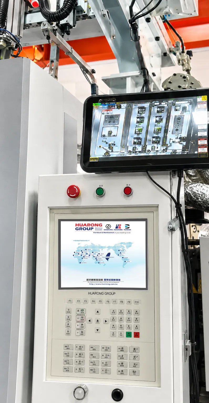 For Production Safety
In Mold Safety Monitoring Series
HCM Series | Featured Model at TaipeiPLAS 2026: HCM500
Monitor in mold conditions in real time and block risks before mold closing.
Explore This Series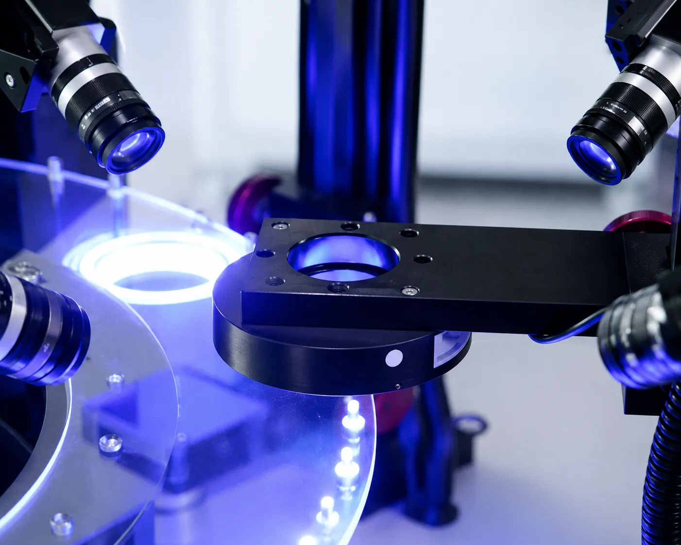 For Quality Reliability
Incoming Material and Product Quality Inspection Series
HCP Series | Featured Model at TaipeiPLAS 2026: HCP600
Inspection solutions are configured around each product. This project specific flexibility is a core capability of the series.
Explore This SeriesSeries 1 · Production Safety
In Mold Safety Monitoring SeriesHCM Series | Featured Model at TaipeiPLAS 2026: HCM500
The camera is not a separate inspection station. It acts as an OK or NG decision point within the injection molding cycle.
A non contact solution that compares in mold conditions in real time to help prevent mold closing on residual parts and related equipment damage. The interface is designed for straightforward operation, supports multiple languages, and includes English as a standard language.
Why Integrate Machine Vision with the Injection Molding Machine?
Many vision inspection systems check the part only after it leaves the molding machine. By then, the defective part has already been produced and the mold may already have closed again.
If a molded part remains in the cavity, an insert is out of position, or ejection is incomplete, failing to detect the condition before mold closing can turn a single defective part into mold damage, unplanned downtime or batch rework.
The key value is stopping the error before the next mold closing action.
Offline inspection can separate defective parts, but it cannot prevent an in mold problem from causing damage. By connecting machine vision to the molding cycle, the inspection result can become a condition for the machine's next action.
The Result Is Inspection Data
The part is inspected only after leaving the machine. Good and defective parts can be separated, but mold related damage or downtime that has already occurred cannot be reversed.
Injection→ Part Removal→ Offline Inspection→ Good / Defective Sorting
The Inspection Result Becomes a Machine Control Condition
Inspection is completed after mold opening and before mold closing. An OK result permits the next cycle. An NG result stops the automatic cycle and triggers an alarm until an operator confirms the condition and resets the system.
Mold Open→ Capture and Inspect→ OK: Continue/ NG: Stop Cycle
Vision inspection can be performed during mold opening, part removal or robot motion. In many applications, this means no additional molding cycle time is required. Actual cycle impact depends on the inspection items and machine motion sequence.
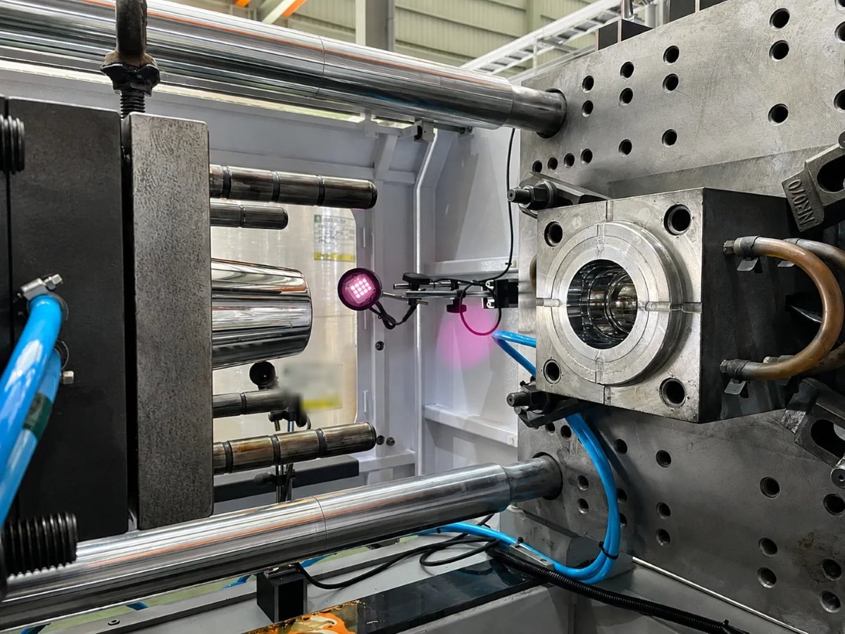
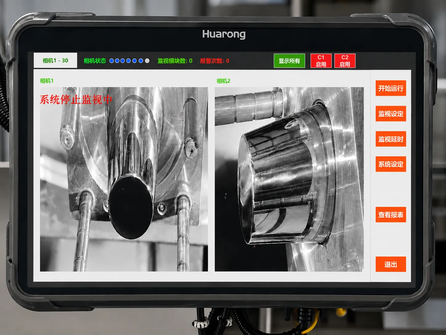
Detectable conditions and inspection criteria depend on product appearance, mold structure and the available camera view. These items are confirmed during the feasibility assessment.
Six In Machine Inspection Checks
The following six checks are performed after mold opening and before mold closing. Results can be returned to the machine through I/O or PLC communication and used as a continue or stop condition.
- Residual Part in Mold Check whether a molded part remains in the cavity.
- Insert Position Verify whether nuts, terminals, pins or other inserts are correctly positioned.
- Ejection Completion Confirm that the part has cleared the mold surface after ejection.
- Part Sticking Detection Detect a part sticking to the mold to reduce the risk of damage during mold closing. Requirement: the camera must cover the full mold surface or the specified inspection area.
- Part Removal Confirmation Detect suction failure or a dropped part during removal.
- Multi Cavity Confirmation Confirm cavity by cavity that all parts have been removed. Requirement: each cavity position must be fixed and within the camera's effective field of view.
Feasibility and inspection criteria for each check must be configured after confirming the mold structure, fixtures and available camera view at the installation site.
Control Sequence
The inspection decision must occur after mold opening and before mold closing. The sequence below shows where the vision system fits within one injection molding cycle.
- 1 Injection Complete Holding pressure and cooling are complete.
- 2 Mold Open The molded part and cavity become visible.
- 3 Ejection Eject the part and trigger image capture.
- 4 Ejection Completion Confirm that the part has cleared the mold surface.
- 5 Vision Inspection Evaluate the configured inspection items.
- 6 OK / NG Output Return the result through I/O or PLC.
- 7 Part Removal or Stop Execute the next action according to the inspection result.
- 8 Next Cycle Mold closing is permitted only when the required conditions are met.
Permit part removal or allow the injection molding machine to enter the next cycle.
Stop the automatic cycle and issue an alarm. The system can be reset only after operator confirmation.
Two Inspections Within One Cycle
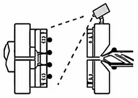
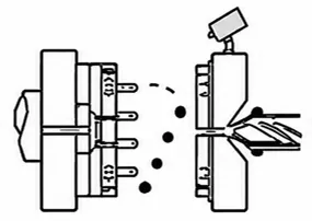
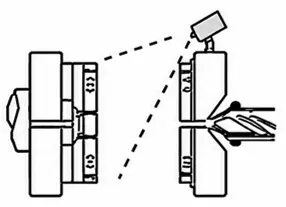
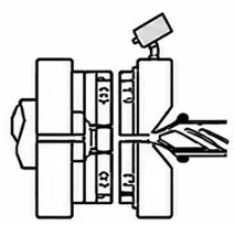
System Architecture: Closed Signal Loop
The signal starts from the machine, passes through the camera and vision controller for inspection, and then returns to the machine. The inspection result becomes actionable only when this closed loop is established.
Minimum Closed Loop Signals ReadyTriggerOKNGAlarmReset
Advanced Integration Cavity IDImagesBatchInspection DataProcess Parameter Correlation
Signals Required for Integration
Only a limited number of machine signals are required. The requirements below are divided into two levels so the system can start with the minimum needed signals and expand later.
Part Sticking / Cavity Check After Mold Opening
- Mold Open Complete
- Cycle Permission After Vision Inspection
If robot part removal also needs to be confirmed, add: Part Removal Complete
Add Signals According to the Production Flow
- Robot Part Removal Complete
- Vision Inspection Enable
- OK/NG
- Abnormal Stop
Cameras, lighting and controllers can be configured according to site conditions. Integration depth depends on the customer's existing PLC and host system.
HCM500 Hardware
In mold monitoring hardware is selected around two practical requirements: clear imaging and stable installation. Infrared lighting reduces interference from visible light, while the mounting structure helps maintain camera position over long term operation.
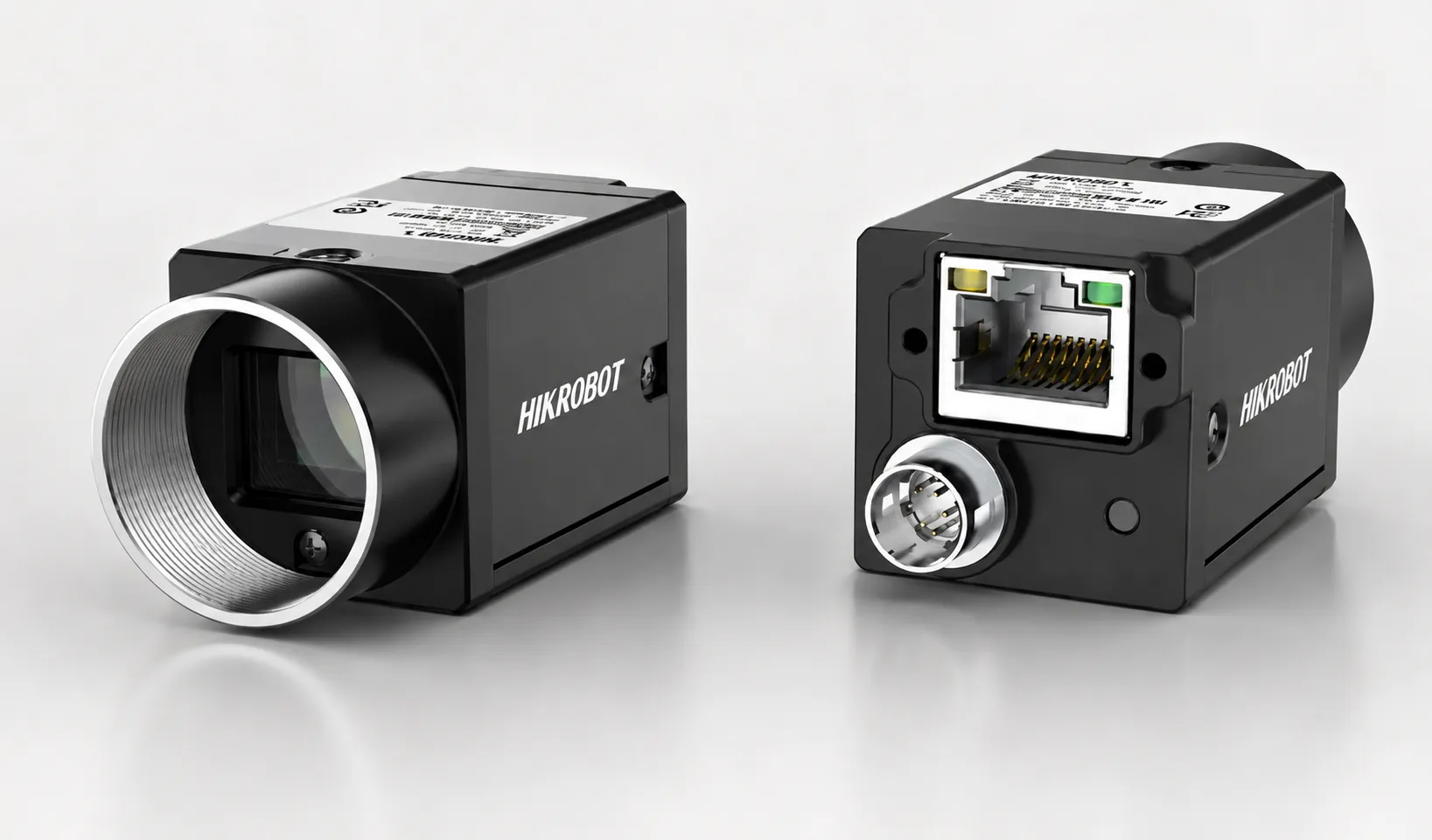
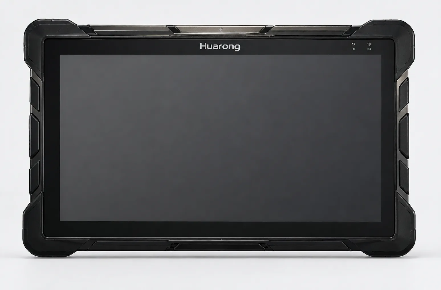
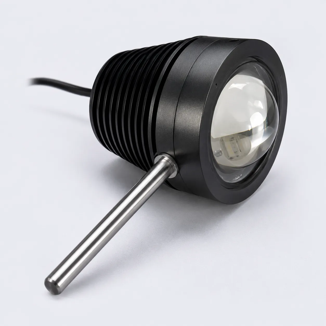
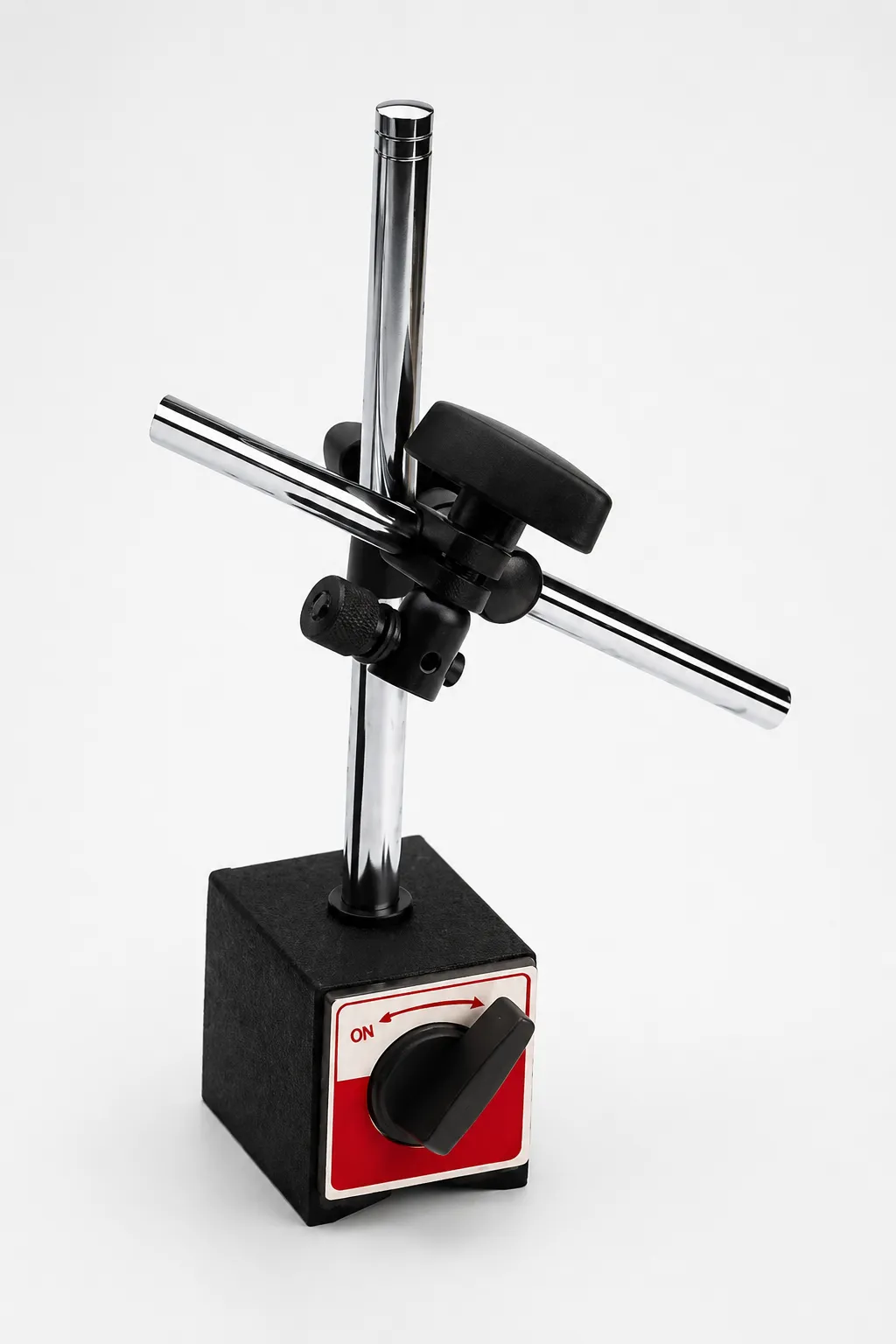
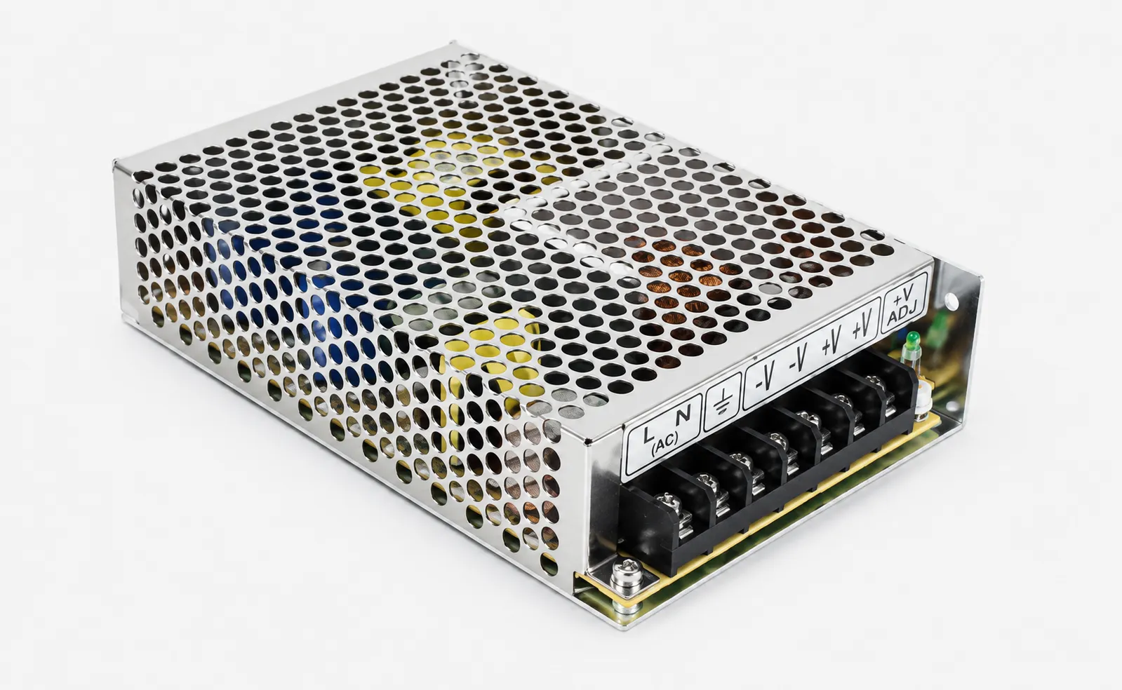
Installation
For production environments, a fixed mounting bracket is recommended to reduce camera position shifts caused by machine vibration. A magnetic base is suitable for installation positioning, testing, adjustment and demonstrations.
The number of cameras, lens focal lengths and lighting types are configured according to the product and inspection items. Contact us for standard configuration details.
Series 2 · Quality Reliability
Incoming Material and Product Quality Inspection SeriesHCP Series | Featured Model at TaipeiPLAS 2026: HCP600
Product appearance inspection does not have a one size fits all configuration. Defect types, tolerance requirements and inspection conditions vary by product. HCP600 configures cameras, lighting and inspection programs according to each application, supports additional camera views when required, and can use AI sample training for defects that are difficult to define with fixed rules. This project specific engineering capability is the core of the series.
The system can also work with robots for vision guided positioning and part handling.
Inspection Capabilities and Real Application Samples
Machine vision, AI and automation are often discussed together, but they are different scopes when defining a quotation and acceptance criteria. The distinctions below reflect how we define them in projects.
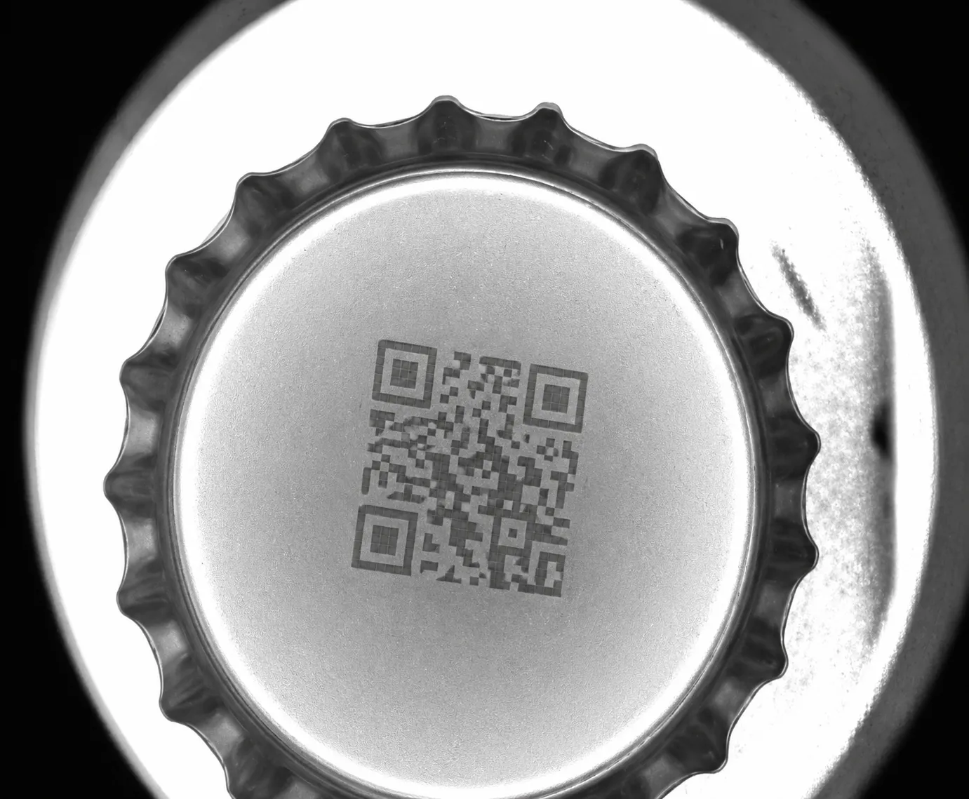
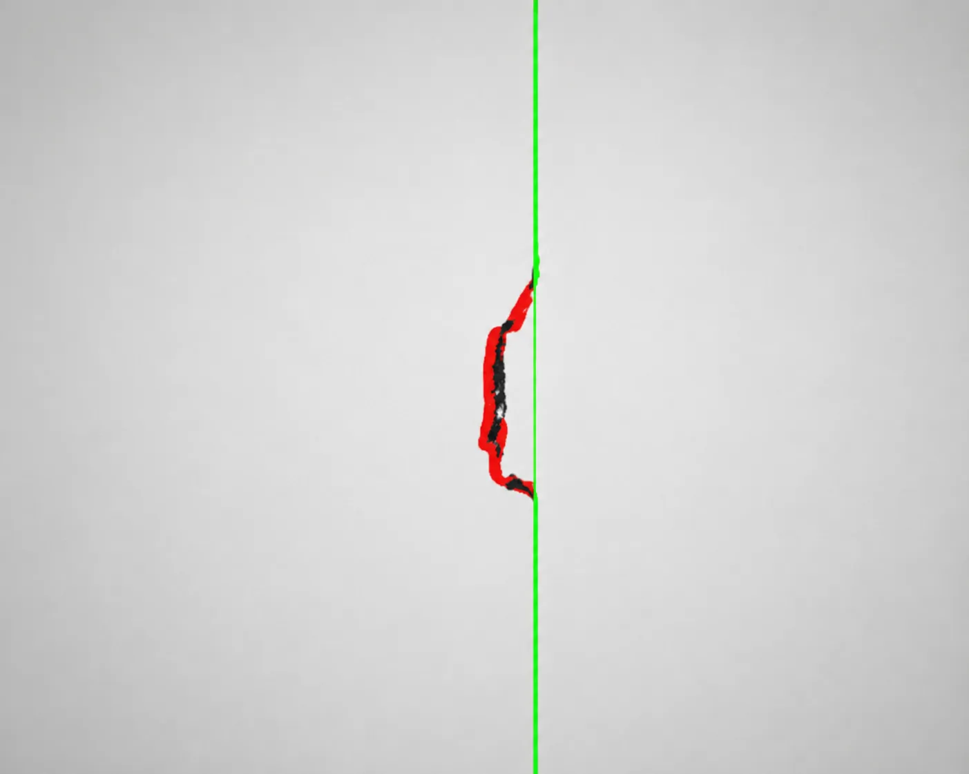
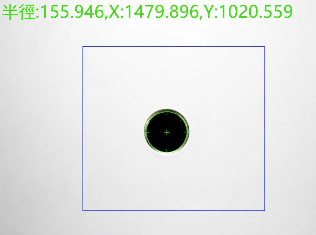
- Machine Vision Dimensions, position, contour, color, code reading, OCR, missing part detection and orientation inspection
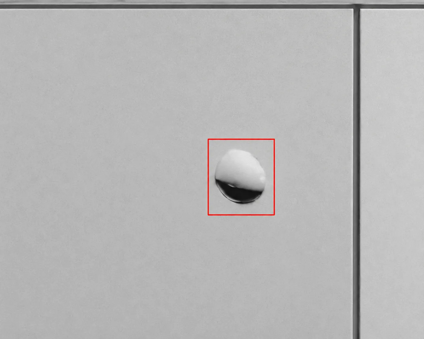
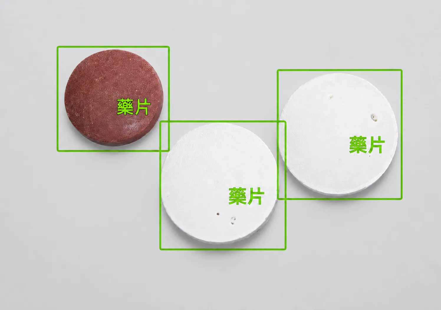
- AI Vision For defect types with significant variation that are difficult to define using fixed rules, sample training or anomaly detection can be used
- Automation Control Part removal, sorting, placement, I/O or PLC interlocks, alarms and stop conditions
Most injection molded part inspection requirements can be handled with conventional machine vision. Items that require sample training are identified during the feasibility assessment.
Inspection Samples
Hardware and Selection Logic
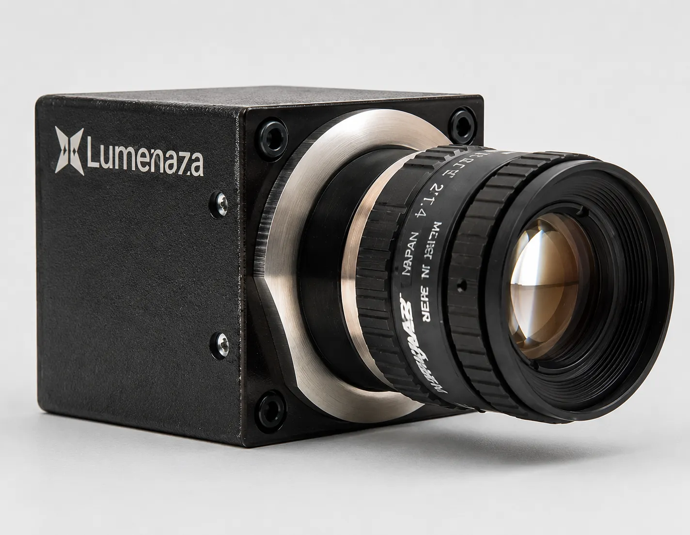
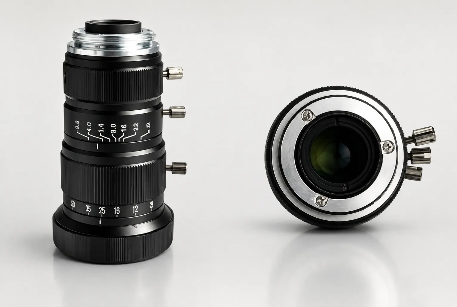
Cameras, lenses, lighting, industrial computers and the operating interface form the common hardware foundation of both series. The difference is in component selection. Cameras and lighting are selected according to the inspection task, while the industrial computer handles inspection logic and signal output.
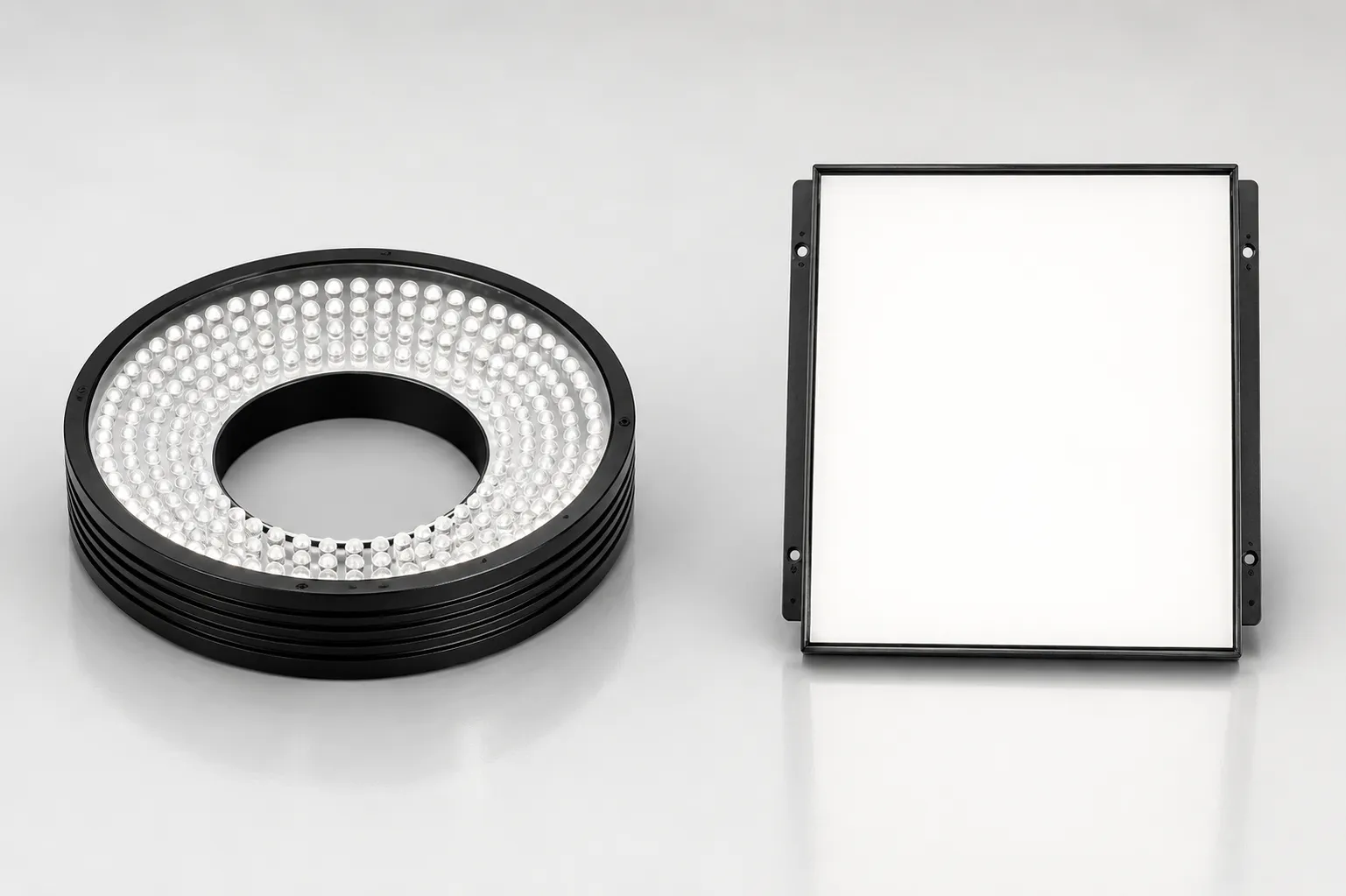
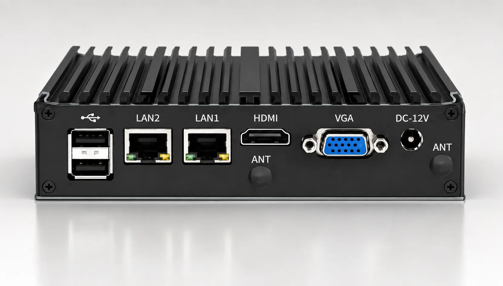
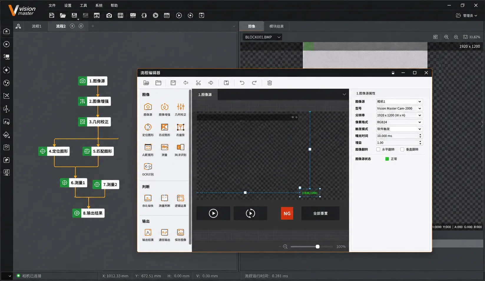
Selection Logic
- Insert Presence 2D Camera + Ring Light or Coaxial Light
- Residual Part in Mold 2D Camera + Fixed Field of View
- Flash / Edge Contour Backlight or Low Angle Dark Field Lighting
- Dimensions / Height Telecentric Lens or 3D Vision
- Reflective / Transparent Parts Polarized, Backlight or Multi Angle Lighting
Inspection stability depends on camera position, fixtures and lighting, not only on the algorithm.
The number of cameras, lens focal lengths and lighting types are configured according to the product and inspection items. Contact us for standard configuration details.
Inspection Is Only the Beginning of the Data Value
The inspection result is more than an immediate continue or stop decision. Stored images and inspection data can become a basis for later process improvement.
Store Images and Inspection Results
Keep each molding cycle traceable.
Defect Statistics and Trends
Track quality changes and identify abnormal trends earlier.
MES Integration Potential
Inspection data can be integrated according to the customer's system architecture and extended into production management and process analysis.
Integration Flexibility
Not every factory needs full traceability from the first stage. Integration can be expanded step by step according to existing equipment and management requirements.
Digital I/O
- Trigger Image Capture
- OK / NG Result
- Alarm Stop
- Reset
PLC / Ethernet
- Cavity ID and Batch
- Inspection Values
- Equipment Status
- Recipe Change
Host System / Traceability
- Image Storage
- Defect Statistics
- Process Correlation
- Audit Data
The vision system can be integrated through I/O, PLC or a host system according to the customer's existing equipment.
Retrofit to Existing Machines
Retrofit integration is generally possible when the existing injection molding machine can provide the required mold open, cycle and safety interlock signals. The controller, available I/O points and safety circuit must still be verified before implementation.
Is Machine Vision Suitable for Your Product?
Send us a product sample or photos. We can help evaluate feasible inspection items and recommend a camera and lighting configuration.
Request a Feasibility AssessmentSend an Inquiry
Complete the information below and our engineering team will contact you as soon as possible.
Thank You for Your Inquiry
Thank you for your inquiry. Our engineering team will contact you as soon as possible.