
Co-Injection Molding Technology
Sandwich / Co-Injection Molding Technology
Create a Skin / Core / Skin layered structure within a single molding cycle, combining surface quality, internal functionality, and greater flexibility in material configuration.
Suitable for injection molding applications that require separate appearance and functional layers, the evaluation of recycled materials in the core, or a layered material strategy.
Exhibition Model: HRM-200 (200 tons)
Inquire Now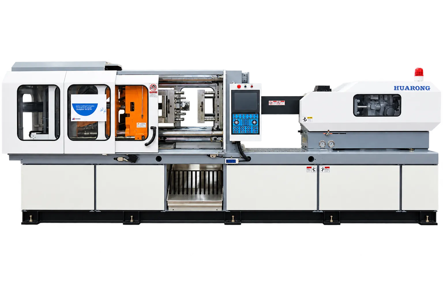
What Is Co-Injection Molding?
Co-injection molding is a multi-material injection molding process in which two materials enter the same mold cavity according to a controlled sequence within a single molding cycle. Depending on the nozzle, runner design, and injection control strategy, the process can form a Skin / Core / Skin sandwich structure or be extended to create split-petal, gradient, and color-mixing effects.
Unlike two-color molding, co-injection places materials in different layers within the same cross-section rather than in separate regions of the part. Key engineering considerations include material changeover timing, flow distribution, layer-thickness control, and shot-to-shot repeatability.
The skin defines the visible surface, while the core is positioned inside. The key concept is layering, not regional separation.
Process Principle: Skin → Core → Skin Sealing
Skin Filling
The skin material first partially fills the mold cavity and flows along the mold wall to form the surface layer, determining the molded part's color, gloss, and surface quality.
Core Injection
The process then switches to the core material, which advances through the center of the melt flow and progressively occupies the central region of the cross-section. Recycled, functional, reinforced, or foamed materials may be evaluated for the core layer.
Skin Sealing
In a three-stage sequence, the skin material can be injected again to seal the gate area and reduce the risk of core exposure near the gate. Whether this third sealing stage is required depends on part geometry, mold design, and appearance requirements.
Molding Result: Skin / Core / Skin Cross-Section
The molded cross-section typically consists of a skin layer surrounding the core. Stable encapsulation depends on wall thickness, corner geometry, gate location, material viscosity differences, and changeover control.
Machine ConfigurationHRM Series Configuration
Skin Injection Unit
Plasticizes, meters, and injects the skin material with independent temperature and speed control to establish the surface quality of the molded part.
Core Injection Unit
Plasticizes, meters, and injects the core material. Recycled, reinforced, or functional materials may be evaluated, subject to material compatibility and processing-window requirements.
Co-Injection Nozzle / Hot Runner
Controls the two melt streams so that they enter the same mold cavity in the required sequence. The need for a dedicated hot-runner system depends on the product, mold structure, and gate design.
Mold / Gate Area
Gate location, runner balance, cavity geometry, and temperature control directly affect layer distribution, core-exposure risk, and appearance repeatability. These are critical factors in feasibility assessment.
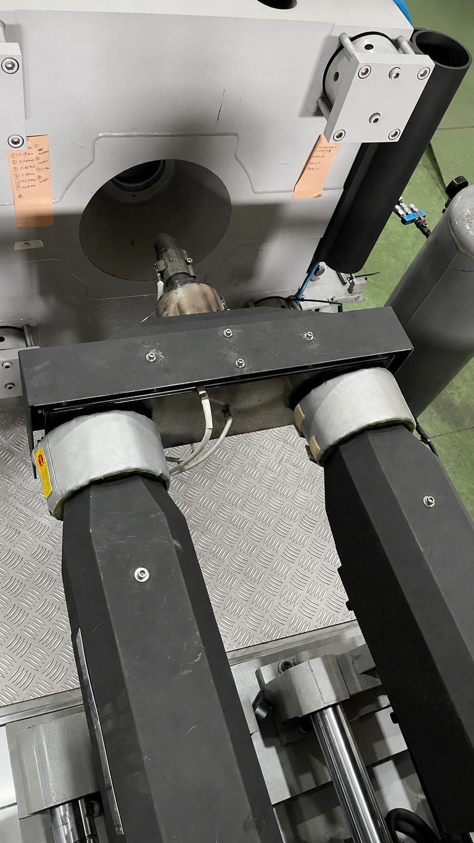
Co-Injection Nozzle Close-Up
A key component that controls how the skin and core materials enter the same mold cavity in the specified sequence to form a stable layered structure.
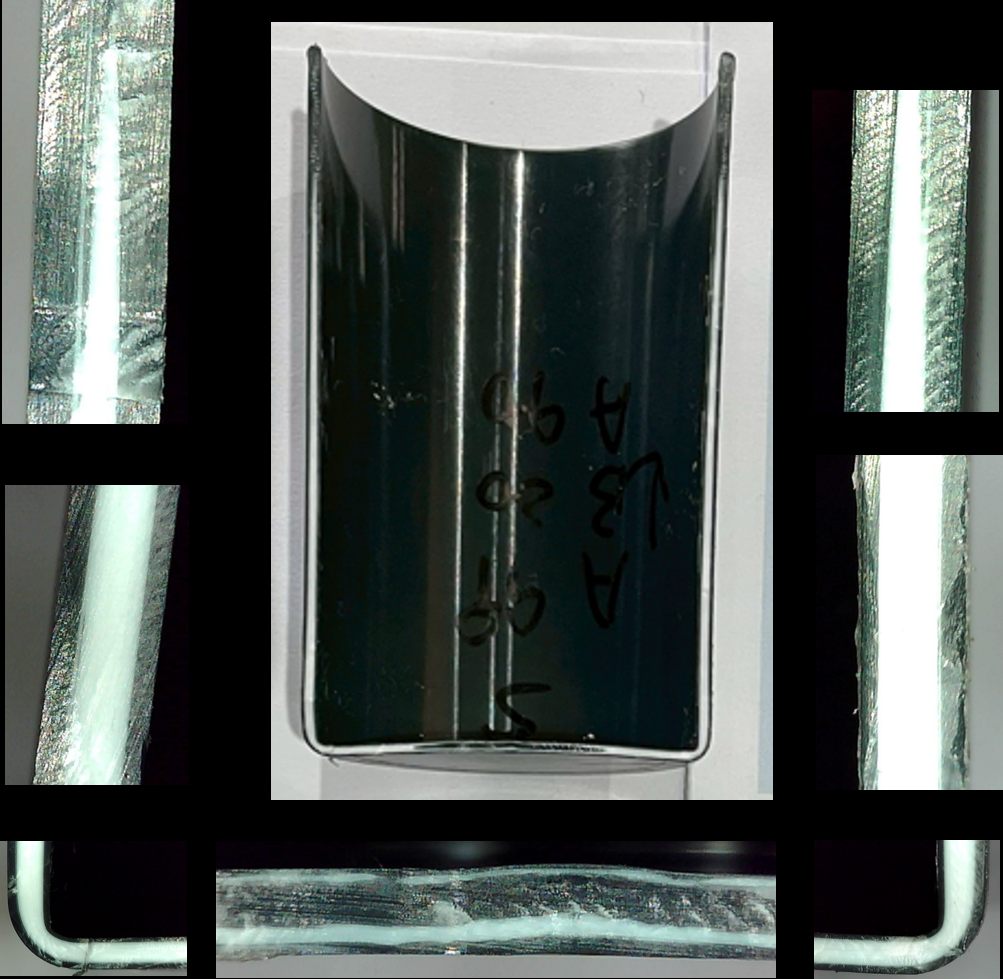
Cross-Section Sample
Cross-section inspection provides a direct view of layer integrity, core centering, and potential issues such as core exposure, interface shift, or local discontinuity.
Key BenefitsKey Benefits
Surface Appearance Control
The skin material defines the visible surface. With appropriate process control, the required color, gloss, and surface quality can be maintained.
Flexible Material Configuration
The core can be configured with recycled, foamed, reinforced, or cost-oriented materials, allowing surface requirements and internal functional requirements to be planned separately.
Functional Layering
Surface requirements such as touch, color, and chemical resistance can be designed separately from core requirements such as stiffness, weight, cost, or sustainability strategy.
Sustainability Potential
Co-injection is often evaluated as a way to use recycled material in the core while maintaining skin-layer surface quality and potentially increasing recycled content.
Cost-Effectiveness Assessment
Actual material-cost reduction depends on wall thickness, core ratio, material price differences, mold and trial costs, production stability, and defect rate. A fixed savings percentage should not be promised before engineering validation.
One Multi-Injection Platform, Multiple Molding EffectsExtended Molding Effects
Depending on nozzle design, runner configuration, injection sequence, and process parameters, the same multi-injection platform can be extended to produce different layered or mixed visual effects. Not every effect can be achieved directly with one standard configuration. Feasibility and stability must be verified based on the mold, nozzle, materials, and mold-trial results.
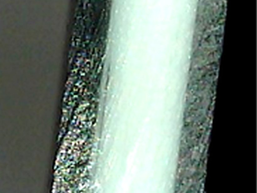
Sandwich / Co-InjectionCo-Injection
The skin surrounds the core and defines the visible appearance, while the inner layer can incorporate functional materials, barrier materials, recycled resin, or foamed material.
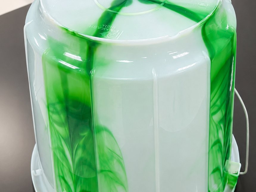
Split-Petal InjectionSplit Injection
Nozzle and runner design distribute different materials into separated regions within the cross-section, supporting distinctive visual effects or functional zoning. Stable molding must be verified through nozzle design and flow-balance validation.
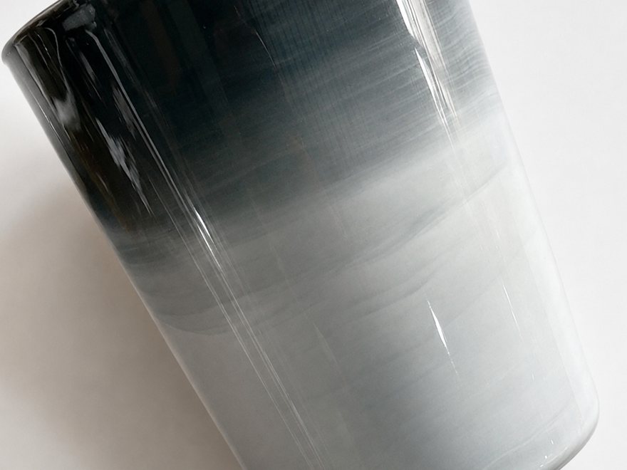
Gradient InjectionGradient
Injection sequence and changeover ratios are controlled to create gradual transitions in color or material. Gradient boundaries and repeatability must be confirmed through mold trials.
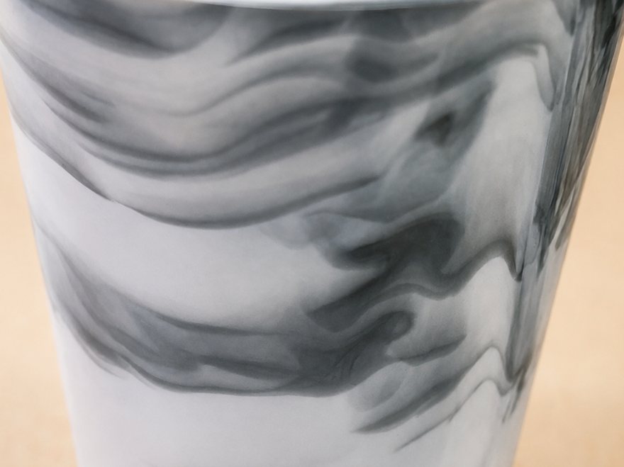
Color-Mixing / Marbling EffectMix-Injection / Marbling
Alternating injections can create naturally mixed, striped, or swirling patterns. These visual effects are more sensitive to injection timing and nozzle conditions.
Applications and Value
Co-injection and color-mixing technologies can produce parts with distinctive visual effects or functional layering, supporting product differentiation and added value. Typical applications include two-color phone cases, mixed-color tableware, marble-effect building materials, decorative products, and customized gifts. Actual effects and appearance stability depend on the product, mold, nozzle, and material conditions.
Comparison of Molding MethodsComparison of Molding Methods
| Method | Material Position | Typical Process | Appearance | Main Purpose |
|---|---|---|---|---|
| Co-Injection Molding | Layered within the same cross-section | Skin → Core → optional Skin Sealing | Surface is typically dominated by the skin material | Layered material strategy, recycled core, functional core |
| Two-Color Molding | Different regions of the same part | First molding step followed by a second injection | Visible two-color or two-material regions | Two-color appearance and localized functions |
| Overmolding | Second material covers the first material | Substrate first, then overmolding | Visible hard-soft material combination | Tactile feel, anti-slip, sealing |
| Insert Molding | Plastic molded around a solid insert | Insert placed before injection | Plastic combined with metal or another insert | Structural integration and electronic-component integration |
Swipe horizontally to view the full table.
Two-color molding separates materials by region; co-injection separates materials by layer.
ApplicabilityApplicability
More Suitable
Products with sufficient wall thickness for stable layered flow, or products that require separate appearance and functional layers. Examples include packaging containers, thick-wall parts, and products designed with recycled material in the core.
Requires Mold Trial and Engineering Evaluation
Household products, industrial containers, automotive parts, selected thin-wall parts, and products with higher appearance requirements require further evaluation based on material, geometry, and gate conditions.
High-Risk Applications
Highly transparent parts, high-gloss parts, appearance-critical parts with very low tolerance for visible interfaces, or material combinations with poor compatibility or excessive processing-temperature differences require more stringent evaluation.
Actual feasibility must be confirmed based on material pairing, part geometry, gate location, mold design, and mold-trial results.
Feasibility AssessmentFeasibility Assessment
Before adopting co-injection molding, begin with a preliminary assessment of four areas: materials, product design, mold, and machine capability.
Materials
Evaluate compatibility between the two materials, interfacial adhesion, processing-temperature windows, viscosity relationship, and whether separate drying and feeding are required. Excessive viscosity differences between skin and core can affect layer stability and appearance.
Product Design
Confirm whether wall thickness is sufficient for stable layering and evaluate process risks at sharp corners, thin sections, thickness transitions, and appearance-critical areas.
Mold
Evaluate gate location, runner design, the need for a dedicated co-injection nozzle or hot runner, multi-cavity balance, and temperature-control conditions. Mold design often directly determines whether the core can be consistently encapsulated.
Machine Capability
Confirm whether shot-volume accuracy, changeover repeatability, speed, pressure, holding-pressure control, and material-feeding stability are sufficient for continuous production.
Limitations and Risks
- 01Material Pairing Limitations: Direct adoption is not recommended when material compatibility is insufficient, processing-temperature differences are excessive, or interfacial adhesion is poor.
- 02Appearance Risk: Thin-wall, highly transparent, high-gloss, or appearance-critical products require particular attention to visible interfaces, changeover marks, and flow marks.
- 03Core Exposure Risk: Unfavorable gate location, large wall-thickness variation, sharp corners, flow imbalance, or poor changeover control may allow the core material to break through the skin and become visible at the surface.
- 04Adoption Cost: Co-injection nozzles, mold modifications, hot-runner systems, mold trials, and validation generally cost more than conventional single-material molding and should be included in the overall investment evaluation.
Not sure whether co-injection is suitable for your product? Share your material combination, product application, appearance requirements, and wall-thickness conditions, and our engineering team can assist with an initial feasibility assessment.
Inquire NowFAQFAQ
What is the difference between co-injection molding and two-color molding?
Two-color molding places two materials in different regions of the part, while co-injection places them in different layers within the same cross-section to form a Skin / Core / Skin structure. The two processes differ in material position, visible appearance, and application purpose.
Can recycled material be used as the core layer?
It can be evaluated. A common approach is to place recycled or reprocessed material in the core while the skin maintains the surface appearance and contact-surface quality. Feasibility still depends on material compatibility, viscosity, moisture content, and application requirements.
How high can the core-material ratio be?
The achievable core ratio depends on part geometry, wall thickness, material viscosity, and process settings. It cannot be defined by one fixed value and must be confirmed through actual mold trials.
What types of products are more suitable for co-injection molding?
Parts with sufficient wall thickness for stable layered flow and products whose appearance and internal functional requirements can be designed separately are generally more suitable. Extremely thin, highly transparent, high-gloss, or interface-sensitive products require stricter evaluation.
Will the core material always remain invisible on the surface?
Not necessarily. Under stable molding conditions, the surface is primarily formed by the skin material. However, unfavorable gate location, wall-thickness variation, corner geometry, material viscosity, or poor changeover control can cause core exposure or visible interfaces. Mold trials and cross-section inspection are required for verification.
Does co-injection molding always require a new mold?
Not always. However, a dedicated co-injection nozzle, gate conditions, runner balance, and temperature-control design typically need to be evaluated. Whether an existing mold can be modified for co-injection depends on the product, mold structure, and appearance requirements.
What validation is recommended before adopting co-injection molding?
Recommended validation includes material-pairing assessment, CAE mold-flow analysis, short-shot testing and mold trials, cross-section inspection, appearance inspection, and functional testing, followed by verification of production repeatability.
HRM-200 SpecificationsSpecifications
The specifications below are based on the HRM-200 exhibition model. Actual configurations can be adjusted according to part dimensions, material combinations, required shot volume, mold interface, and automation requirements.
| Item | Unit | HRM-200 |
|---|---|---|
| Injection Unit | ||
| Screw Diameter | mm | 32×2 |
| Injection Pressure | kg/cm² | 2030×2 |
| Shot Volume | cm³ | 128×2 |
| Shot Weight (PS) | g | 117×2 |
| Shot Weight (PS) | oz | 4.1×2 |
| Injection Speed | mm/sec | 121×2 |
| Injection Rate | cm³/sec | 97×2 |
| Clamping Unit | ||
| Clamping Force | Tons | 200 |
| Tie Bar Distance (H×V) | mm | 505×505 |
| Opening Stroke | mm | 465 |
| Mold Thickness | mm | 130~520 |
| Mold Platen (H×V) | mm | 715×715 |
| Ejector Stroke | mm | 140 |
| Mold Hole | mm | 100 |
| Electrical & Other Equipment | ||
| Servo Motor | kW | 12×2 |
| Number of Heating Zones | Zones | 11 |
| Total Heating Wattage | kW | 21.4 |
| System Pressure | kg/cm² | 140 |
| Oil Capacity | L | 390 |
| Machine Dimensions (L×W×H) | m | 5.5×1.6×1.8 |
| Machine Weight | Tons | 6.5 |
Specifications are subject to change without prior notice due to ongoing product development and improvement.
Technical Support and Implementation AssistanceTechnical Support
Product Suitability Assessment
Assess the feasibility of co-injection based on product application, appearance requirements, material strategy, and wall-thickness conditions.
Machine Configuration Recommendation
Plan injection-unit configuration, co-injection nozzle design, control logic, and peripheral material-feeding conditions according to product and mold requirements.
Mold and Process Integration
Integrate mold design, hot-runner requirements, material selection, and CAE analysis to establish a practical mold-trial and implementation path.
Mold Trial and Parameter Setup
Support the setup of Skin / Core / Skin changeover conditions, injection profiles, mold-trial validation procedures, and production-stabilization strategies.
Co-injection is suitable for products that benefit from a layered material strategy, but adoption should ultimately be based on engineering validation, appearance results, and production stability.
Certifications
HUARONG GROUP Corporate Introduction Video
A dedicated co-injection molding machine video is currently in production and will be added when available.
Want to Evaluate Whether Co-Injection Is Right for Your Product?
If your product must balance surface quality, internal functionality, and material strategy, begin by evaluating material pairing, wall thickness, appearance requirements, and mold design. Early engineering assessment can help shorten the decision-making process before mold trials and implementation.
Inquire NowInquiryInquiry
Please complete the form below. Our engineering team will contact you as soon as possible.
Thank You for Your Inquiry
Thank you for contacting us. Our engineering team will get in touch with you as soon as possible.